Glossary
A bitmap image that make a surface appear bumpy in a rendered image. Bumpmaps do not modify the shape of the surface.
A construction plane is like a tabletop that the cursor normally moves on. The construction plane has an origin, x- and y-axes, and a grid. The construction plane can be set to any orientation, and each viewport’s construction plane is independent of those in other viewports.
The construction plane represents the local coordinate system for the viewport and can be different from the world coordinate system.
Rhino’s standard viewports come with construction planes that correspond to the viewport. The default Perspective viewport, however, uses the world Top construction plane, which is the same construction plane that is used in the Top viewport.
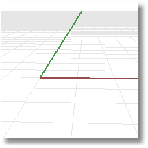
The construction plane grid lies on the construction plane. The dark red line represents the construction plane x-axis. The dark green line represents the construction plane y-axis. The red and green lines meet at the construction plane origin. The color of these lines can be changed.
To change the direction and origin of a construction plane, from the menu, use the CPlane command. Preset construction planes: World Top, Right, and Front give you quick access to common construction planes. In addition, you can save and restore named construction planes and import named construction planes from another Rhino file.
Coordinate input, elevator mode, object snaps , and other cursor constraints allow the cursor to move away from the construction plane.
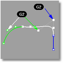
Continuity describes the relationship between curves and surfaces.
Each level of continuity assumes the conditions for the previous level are met.
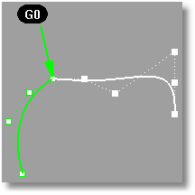
Position measures location only. If the end points of each curve are in the same location in space, the curves are position continuous (G0) at the ends.
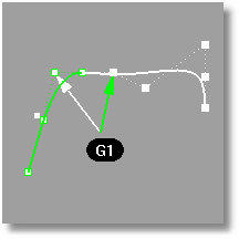
Tangency measures position and curve direction at the ends. The direction is determined by the first and second point on each curve. If these all fall on a line then two curves are tangent (G1) at the ends.
Curves and surfaces with G1 continuity are also G0 continuous.
Curvature continuity between two curves measures position, direction, and radius of curvature at the ends. If the radius of curvature is the same at the common end point, curves are curvature continuous (G2). This condition is not easy to determine by just looking at where the points are located.
Curves and surfaces with G2 continuity are also G1 and therefore G0 continuous.
Tools for testing continuity
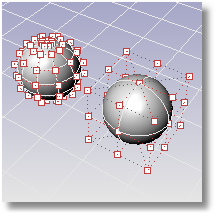
Control points are coefficients of NURBS basis functions. Sometimes also called control vertex or node.
Control points are markers or "grips" on objects such as curves, surfaces, lights, and dimensions and cannot be separated from their objects.
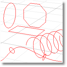
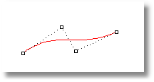
Curves include straight lines, polylines, arcs, circles, polygons, ellipses, helixes, and spirals. Curves have a direction.
Curves have control points that determine the shape of the curve.
A polynomial is a function like y = 3·x3 – 2·x + 1. The "degree" of the polynomial is the largest power of the variable. For example, the degree of 3·x3 – 2·x + 1 is 3; the degree of – x5 + x2 is 5, and so on. NURBS functions are rational polynomials and the degree of the NURBS is the degree of the polynomial. From a NURBS modeling point of view, the (degree – 1) is the maximum number of "bends" you can get in each span.
For example
A line has degree 1. It has zero "bends."
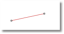
Degree 1: line.
A parabola, hyperbola, arc, and circle (conic section curves) have degree 2. They have one "bend."
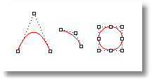
Degree 2: parabola, arc, circle.
A cubic Bézier has degree 3. If you arrange its control points in a zig-zag shape, you can get two "bends."
Degree 3 curve.
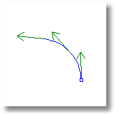
Direction
For curves, the direction is determined originally by the start and end points specified when it was drawn.
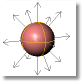
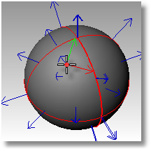
For surfaces the normal is a direction that points toward what you can think of as "outside" or "up." For closed polysurface (cone, cylinder, box, etc.) or single-surface solids (sphere, torus), the normal always points "out." However, on an open surface or polysurface, the direction of the normal depends on how it was created and can seem arbitrary.
The Dir command displays an object's normal direction.
|
|
|
|
|
|
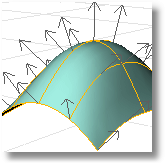
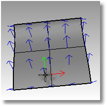
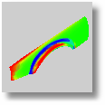
Every surface is roughly rectangular. Surfaces have three directions, u, v, and normal. You can display the u- and v-directions and the normal direction with the Dir command.
The u- and v-directions are like the weave of cloth or screen. The u-direction is indicated by the red arrow, and the v-direction is indicated by the green arrow. The normal direction is indicated by the white arrow. You can think of u-, v-, and normal-directions as corresponding to the x, y, and z of the surface.
These directions are used when mapping textures and inserting knots.
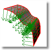
A circular surface can be like a spider web with one direction converging in the center.
The domain is the set of all possible input values to the function that defines the curve or surface.
Points on a NURBS curve evaluated at knot averages.
For example, if the curve degree is three and the knot vector is:
0, 0, 0, 1, 2, 3, 3, 3
the edit points are points on the curve evaluated at these parameter values:
0, 1/3, 1, 2, 8/3, 3
The edge of a surface or mesh polygon. Surface edges can be either trimmed or untrimmed. If trimmed the underlying surface will generally extend past the edge.
An edge that is not the result of a trim curve on the surface. The 'natural' edge or outer bounds of a surface. The underlying surface will not extend past an untrimmed edge.
A surface or polysurface edge that is not connected to another edge. Solid objects have no naked edges.
A technique that uses color to display non-chromatic properties of a surface. The CurvatureAnalysis, DraftAngleAnalysis, and ThicknessAnalysis commands use false color analysis.
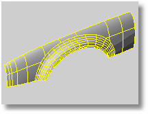
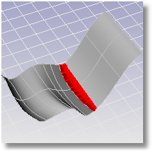
An isoparametric curve (isocurve) is a curve of constant u- or v-value on a surface. Rhino uses isocurves and surface edge curves to visualize the shape of a NURBS surface. By default isocurves are drawn at knot locations. If the surface is a single knot-span surface like a simple rectangular plane, isocurves are drawn also in the middle of the surface.
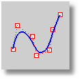
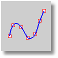
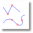
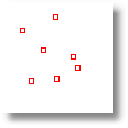
A kink is a point where a curve dramatically changes direction. The corners of a rectangle are kinks. Kinks can also happen at a point where a curve dramatically changes its the amount it curves. For example a rounded rectangle has kinks where the line segments turn into arcs.
The red points mark the locations of kinks in the curves.
A value of the curve parameter where the polynomial definition of the b-spline changes. Non-uniform knot vectors allow any spacing of the knots, including multiple knots (adjacent knots with the same value).
Imagine a rope. If you hold it at the ends, the rope will sag according to the laws of nature (gravity, the stiffness of the rope, etc.) with a polynomial definition. If you tie it off somewhere along its length (by putting knots in it), there will be a different polynomial definition (sag) for each segment between the knots.
Knot points are points on curves where it is the most convenient to place end points of cross-section curves for surface creation commands like Sweep2 and NetworkSrf. A large part of Rhino's powerful proprietary surface geometry engine is devoted to calculating surfaces when cross-section curves are not at knot points. This lets the designer think about things like shape and form instead of worrying about math geek details like knot vectors. However, knot snap is provided for those users who like to locate features at knots.
Degree number of knots at a location, which is as many as are possible. There may be a kink at that point that is desired.
A collection of vertices and polygons that define the shape of an polyhedral object. Meshes in Rhino consist of triangles and quadrilaterals.
The location where the edges of the mesh faces meet. The mesh vertex (plural vertices) contains x-, y-, and z-coordinates and may contain a vector normal, a color value, and texture coordinates.
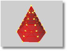
Rhino creates triangles and quadrilaterals meshes for export into various file formats. When surfaces are joined together in Rhino, the meshes along the joined edge have coincident vertices. If a mesh is generated from a solid, there will be no holes in the mesh. This is valuable for export to STL rapid prototyping files.
NURBS stands for non-uniform rational basis-spline. It is a mathematical way of defining curves, surfaces, and solids. For more information, see About NURBS. There are also many sites on the Internet with explanations about NURBS curves and surfaces. Use your favorite search engine to find them.
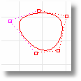
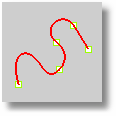
A periodic curve is a smooth closed curve. Periodic curves stay smooth when you edit them.
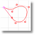
Non-periodic curve
A non-periodic curve is a closed curve with a kink at the start/end of the curve. Deforming non-periodic curves near the start of the curve may result in kinks.
Periodic surfaces are closed surfaces (such as a cylindrical surface) that can be deformed without developing kinks. Periodic surfaces are automatically created when the input curves are periodic.

Non-periodic surface
A non-periodic surface is a closed surface with a kink at the start/end of the surface. Deforming non-periodic surfaces near the start of the surface may result in kinks. Non-periodic surfaces are automatically created when the input curves are non-periodic.

Point objects mark a single point in 3 D space. Points are the simplest objects in Rhino. Points are most often used as placeholders. They are placed with point drawing commands They can be located with the Point object snap and manipulated with transform commands. Point objects are not the same as control points.
A curve consisting of two or more curves joined together.
Polycurve with points at the connections.
A polysurface consists of two or more surfaces joined together. If the polysurface fully encloses a volume, it is also a solid.
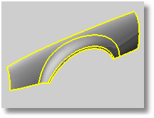
Polysurface edges highlighted.
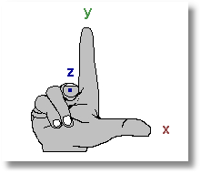
Demonstrates the direction of the construction plane z-axis. Form a right angle with the thumb and forefinger of your right hand. When your thumb points in the positive x-direction, your forefinger points in the positive y-direction, and the palm of your hand faces in the positive z-direction.
Any surface or polysurface that is closed and has no naked edges defines a solid.
Rhino creates two types of surfaces: NURBS and rational.
A NURBS surface is like a rectangular stretchy rubber sheet. The NURBS form can represent simple shapes, such as planes and cylinders, as well as free-form, sculptured surfaces. All NURBS surfaces have an inherently rectangular organization.
Rational surfaces include spheres, cylinder sides, cones. These surfaces are determined by their center and radius rather than a polynomial representation.
Texture mapping coordinates are two-dimensional coordinate values attached to polygon mesh vertices. They define which pixel in the texture map is attached to which vertex on polygon mesh. All the other points on the polygon mesh in the rendered image are interpolated from the vertex points.
UV texture mapping coordinates used by Rhino mean that every polygon mesh vertex has its own two-dimensional texture mapping coordinate based on the parameterization of the NURBS surface the polygon mesh is created from.
Rhino automatically applies UV texture mapping coordinates to all polygon mesh objects created from NURBS surfaces.
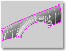
A trimmed surface has two parts: a surface that defines the geometric shape and trimming curves that mark sections of the underlying surface that are removed from view.
Trimmed surfaces are created with commands that trim or split surfaces with curves and other surfaces. Some commands create trimmed surfaces directly. Since it can be important for you to know if a surface is trimmed, the Properties command lists the trimmed or untrimmed state of the surface. Some Rhino commands work only with untrimmed surfaces and some rendering software does not import trimmed NURBS surfaces.
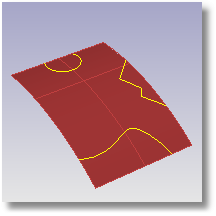
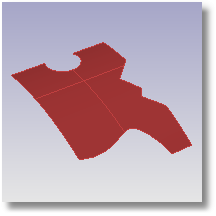
Trimming curves lie on the underlying surface. This surface may be larger than the trim curves, but you will not see the underlying surface because Rhino does not draw anything for the part of the surface that is outside the trim curves.
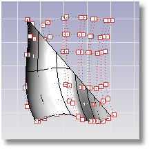
Every trimmed surface retains information about its underlying surface geometry. You can remove the trimming curve boundaries to make the surface untrimmed with the Untrim command.
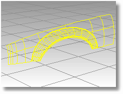
Surfaces and solids are represented as 3-D curves that look like wires wrapped around the surface. The wireframe consists of edge curves and isoparametric curves. Use the WireframeViewport command to view the object in wireframe mode.
Rhino contains one world coordinate system. The world coordinate system is independent of the construction plane of the active viewport and cannot be changed. The arrow icon in the lower left corner of each viewport displays the direction of the world x-, y-, and z-axes. The arrows move to show the orientation of the world axes when you rotate a view.